Size Membranes With 20–30% Margin: TFF Basics for Bioprocessing
Tangential flow filtration (TFF) is a crossflow membrane process that concentrates, diafilters, and clarifies biological streams while limiting membrane fouling. Feed runs parallel to the membrane surface instead of straight into it, so retained material gets swept along rather than packed against the pores. The two levers you’ll tune constantly are transmembrane pressure (TMP) and crossflow rate, and the two module formats you’ll meet most often are flat-sheet cassettes and hollow fiber. Everything else in this article builds on that.
TL;DR:
- Operating beyond the flux plateau caused by concentration polarization wastes energy and accelerates fouling without improving throughput.
- Membrane format choice depends on product sensitivity: hollow fiber modules suit shear-sensitive viral vectors and nanoparticles, while cassettes are better for robust proteins.
- Scaling up should preserve TMP, crossflow, and shear exposure per unit area, with stress-testing and data logging crucial for maintaining process consistency.
- Fouling signals include decreasing flux at constant TMP and increasing pressure drop across the module, requiring timely cleaning or process adjustment.
- Proper membrane selection involves testing with actual product, considering MWCO, shear tolerance, viscosity, and cleaning compatibility; guidelines are only starting points.
Table of Contents
- Understanding Tangential Flow Filtration: Flow Geometry and Fouling
- Membrane Formats and Materials: Cassettes, Hollow Fiber, and Ceramic
- Key Operating Parameters: TMP, Flux, Crossflow, and VCF
- Where TFF Fits in Bioprocessing Workflows
- How to Choose a Membrane and Module Format
- Building a TFF System: Pumps, Gauges, and Filtrate Control
- Scaling Up Without Losing Process Behavior
- Recognizing Fouling and Basic Cleaning Considerations
- A Basic Lab Workflow for Concentration and Diafiltration
- What Actually Trips Up Bioprocessing Teams on TFF
- Support for Labs Running TFF Workflows
- Reagents and QC Support That Complement Your TFF Workflow
- Sources
- FAQ
Understanding Tangential Flow Filtration: Flow Geometry and Fouling
The defining feature of tangential flow filtration is direction. Feed moves parallel to the membrane surface, not perpendicular to it, and that sweeping action is what separates TFF from ordinary filtration. The stream splits into two outputs: permeate, the portion that passes through the membrane, and retentate, the portion that stays on the feed side and recirculates. Retention or rejection describes how well the membrane holds back a target molecule while letting smaller species through.
Two forces govern the process. TMP is the average pressure pushing fluid through the membrane, measured across feed, retentate, and permeate ports. Crossflow is the recirculation rate that keeps the feed side moving and prevents solids from settling on the membrane. Flux, expressed in liters per square meter per hour (LMH), is the rate of permeate passing through per unit of membrane area. As solute concentrates near the membrane wall faster than it diffuses back into the bulk stream, a phenomenon called concentration polarization sets in. This is the physical basis for why flux does not rise forever, no matter how much you push TMP.
That plateau behavior is one of the most consistent things you’ll see on the bench. Push TMP higher and higher, and flux climbs at first, then flattens, then can even fall as the polarized layer thickens into a gel-like resistance layer. The Pall technical report on TFF fundamentals describes this sweeping action as the core mechanism that lets TFF handle size-based separations across a huge range of volumes, from milliliter bench runs to production batches.
Statistic Callout: In most protein concentration runs, flux increases roughly linearly with TMP at low pressures, then plateaus once concentration polarization dominates. Operating past that plateau wastes pump energy and accelerates fouling without gaining meaningful throughput.
Dead-end (normal flow) filtration sends the entire feed stream straight through the membrane, so retained solids build a cake layer that thickens until the filter clogs. It’s simple and cheap, and it works fine for one-time clarification of dilute streams. TFF costs more in hardware and setup, but it sustains flux over long runs and recovers product from the retentate side, which dead-end filtration cannot do.
What that plateau behavior means in daily operation:
- Running above the flux plateau burns pump capacity without gaining throughput.
- Fouling accelerates once you cross into the polarization-dominated zone.
- Diagnostic flux trials before a full run save far more time than they cost.
- The plateau point shifts with viscosity, temperature, and product concentration, so it isn’t a fixed number across batches.
Membrane Formats and Materials: Cassettes, Hollow Fiber, and Ceramic
Module geometry decides how much shear your product sees and how easily the system cleans between runs. Three formats cover almost every bioprocessing application.
Flat-sheet cassettes stack membrane sheets with feed channels between them, often with turbulence-promoting screens. That turbulence boosts flux and resists fouling, which makes cassettes the default choice for high-throughput protein and monoclonal antibody concentration. The tradeoff is higher shear at the channel surface, which can stress fragile particles.
Hollow fiber modules run feed through the lumen of bundled tubes. Shear stays lower and more uniform than in a cassette, and hold-up volume drops sharply, both of which matter when you’re processing a small, precious batch of a shear-sensitive product. Enveloped viruses, extracellular vesicles, and some nanoparticle formulations tend to do better in hollow fiber for exactly this reason.
Ceramic and tubular modules trade some flux efficiency for ruggedness. They tolerate aggressive cleaning-in-place (CIP) chemistry, extreme pH swings, high temperatures, and heavy solids loads that would degrade a polymeric membrane over repeated cycles. That durability comes at a price premium and generally lower packing density than cassettes.
Membrane chemistry matters as much as format. Polyethersulfone (PES) is common for its broad chemical compatibility and low protein binding. Regenerated cellulose offers a hydrophilic surface that resists nonspecific adsorption, useful when you’re worried about losing yield to the membrane itself. Surface coatings can further tune fouling resistance and cleaning compatibility, but they also narrow your CIP chemistry options. Choosing membrane chemistry and geometry that match the biochemical stability of the target matters most for sensitive modalities like mRNA and lipid nanoparticles, according to Bioprocess Online’s review of membrane chemistry in TFF.
A quick summary of where each format tends to land:
- Cassettes: highest flux density, higher shear, best for robust proteins and mAbs at scale.
- Hollow fiber: lowest shear and hold-up, best for shear-sensitive viral vectors and nanoparticles.
- Ceramic/tubular: best chemical and thermal ruggedness, best for harsh feeds or aggressive CIP cycles.
Pro Tip: Run a small hollow fiber comparison alongside your cassette trial whenever the product is a virus, exosome, or lipid nanoparticle. A 10% yield difference at bench scale often becomes a much larger gap once you multiply by production volume.
Key Operating Parameters: TMP, Flux, Crossflow, and VCF
TMP is calculated from the pressures at three points around the module:
TMP = (P_feed + P_retentate) / 2 − P_permeate
Feed and retentate pressure gauges sit at the module inlet and outlet; permeate pressure is measured at the filtrate line, often near atmospheric in gravity-drained setups. Getting TMP right depends on placing gauges where the manufacturer’s spec sheet says to, because a few centimeters of tubing height can skew a low-pressure reading.
Flux (J) is permeate flow rate divided by membrane area, reported in LMH. Flux rises with TMP until concentration polarization caps it, per the flux-plateau behavior described earlier. Crossflow, or recirculation rate, is the flow moving parallel to the membrane. Raising crossflow generally raises the achievable flux at a given TMP because it disrupts the polarized boundary layer, but it also means more pump passes per unit time, and more pump passes means more mechanical shear on the product. The InnovateBio technical brief on membrane-based TFF frames this directly: higher crossflow buys you flux, but it costs you in shear and hold-up loss, and balancing the two is the practical heart of TFF operation.
Volume concentration factor (VCF) measures how much you’ve reduced feed volume:
VCF = Initial feed volume / Current retentate volume
Diafiltration volumes (DV) track buffer exchange progress the same way, counting how many retentate-equivalent volumes of new buffer have passed through the system. Membrane area sizing for a new process typically follows:
A = V / (J × T)
where V is the batch volume to process, J is the flux measured at your intended TMP and crossflow during lab trials, and T is your target processing time. The Pall report’s sizing guidance recommends building in a safety margin here, since production-scale flux almost always runs lower than the clean bench numbers you measured with a small membrane swatch.

Statistic Callout: A protein concentration run with a measured lab flux processing 10 liters in a reasonable target window needs a certain membrane area, before adding a safety margin for scale translation.
A worked sequence for sizing a small run:
- Measure flux at your target TMP and crossflow on a small membrane swatch.
- Plug that flux, your batch volume, and your target processing time into A = V / (J × T).
- Add a margin (commonly 20 to 30 percent) to account for lower production-scale flux.
- Confirm the resulting area matches an available cassette or fiber cartridge size.
Where TFF Fits in Bioprocessing Workflows
Concentration and diafiltration together form the backbone of most downstream protein and monoclonal antibody processes. You concentrate to reduce volume, then diafilter to exchange the process buffer for a formulation buffer, all without ever removing the product from the system. Endpoint checks typically include mass balance, final protein concentration by UV absorbance, and aggregate levels by size-exclusion chromatography.
Clarification and cell harvest workflows use TFF, sometimes with a hollow fiber module, to separate cells and cell debris from the product-containing supernatant before it moves into a polishing step. A coarse prefilter ahead of the TFF module extends membrane life considerably when the feed carries heavy particulate load.
Viral vectors and lipid nanoparticles need the gentlest possible handling, since both product classes lose potency under excess shear. Hollow fiber format with a membrane chemistry chosen for low adsorption tends to be the safer starting point here, echoed by the same shear-sensitivity guidance covered under membrane materials.
Buffer exchange and desalting are pure diafiltration exercises, distinct from concentration, and the Cytiva technical report on TFF applications notes that TFF can combine concentration and diafiltration in one system, saving time and reducing product loss compared with running them as separate unit operations. Planning your DV target differs by objective: a concentration step just needs enough volume reduction, while a diafiltration step needs enough buffer turnovers to reach the residual solute level your formulation requires.
- Concentration/diafiltration: proteins, mAbs, peptides moving toward formulation.
- Clarification/cell harvest: removing cells and debris ahead of polishing.
- Viral vectors/nanoparticles: low-shear hollow fiber, gentle membrane chemistry.
- Buffer exchange/desalting: infiltration-only runs with DV targets set by residual solute spec.
How to Choose a Membrane and Module Format
Start with the product, not the hardware. Molecular weight, shear sensitivity, feed viscosity, solids load, throughput target, and whether the system needs to be single-use or reusable all shape the decision before you even open a catalog.
- Identify the target molecule’s molecular weight and shear tolerance.
- Pick a membrane MWCO roughly three to six times lower than the target protein’s molecular weight to ensure solid retention with reasonable flux.
- Match module format to shear sensitivity: hollow fiber for fragile targets, cassette for robust ones needing high throughput.
- Check viscosity and solids load; high-solids or high-fouling feeds push toward ceramic or a coarser prefilter stage.
- Confirm CIP chemistry compatibility with the membrane material before committing to a format.
The Bionet white paper on membrane selection frames the decision tree the same way: shear sensitivity and viscosity are the first filters, cleaning and fouling tendency come second. A 30 kDa target protein, for example, typically pairs with a membrane rated around 10 kDa MWCO, not one rated close to 30 kDa, because retention efficiency drops sharply as the ratio narrows.
Pro Tip: Never trust a manufacturer’s MWCO rating as a guarantee of retention for your specific molecule. Run a small lab-scale trial with your actual product and check retentate versus permeate concentration by whatever assay you’d use for final QC, since shape and charge shift real-world retention more than the nominal rating suggests.
Building a TFF System: Pumps, Gauges, and Filtrate Control
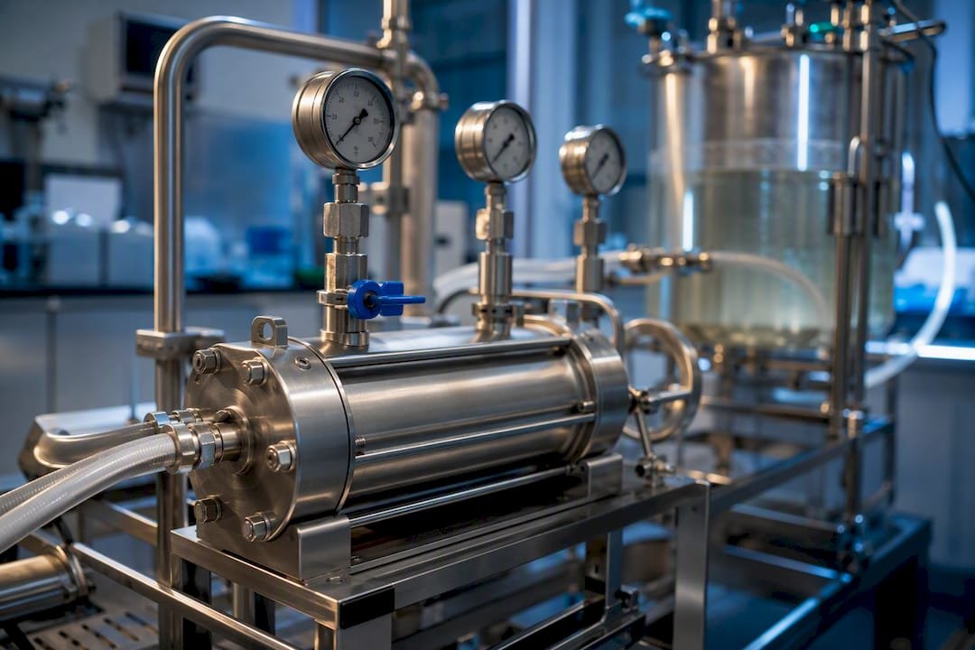
A working TFF setup needs a feed reservoir, a recirculation pump, the membrane module itself, and pressure gauges at three points: feed inlet, retentate outlet, and permeate line. Peristaltic pumps dominate lab and pilot scale because they’re gentle, easy to sanitize, and simple to calibrate; diaphragm or rotary lobe pumps take over at larger production volumes where peristaltic tubing becomes impractical.
Gauge placement isn’t cosmetic. Feed and retentate pressures feed directly into the TMP calculation, and a permeate gauge tells you whether the filtrate line is running near atmospheric or building backpressure that would throw off your TMP math.
Filtrate control, meaning a filtrate pump or valve that actively regulates permeate flow rather than letting TMP alone drive it, protects open ultrafiltration membranes from spiking into near-dead-end behavior during startup. That startup window is exactly when fouling risk is highest, since flux is uncontrolled until the system stabilizes.
- Match tubing internal diameter to pump head specs to avoid cavitation at higher flow rates.
- Keep hold-up volume in mind for small batches; long tubing runs can lose meaningful product to dead volume.
- Place the permeate gauge close to the module, not far downstream, for an accurate reading.
- Use filtrate control on open UF membranes rather than relying on TMP alone during startup.
Scaling Up Without Losing Process Behavior
Scale-up fails most often when teams multiply membrane area and assume everything else holds constant. It doesn’t. The right approach preserves the operating window, meaning TMP, crossflow per unit area, and shear exposure, rather than treating area as the only variable that changes.
A platform-based approach works better in practice: define the operating window at lab scale, stress-test it at pilot scale under intentionally pushed conditions, and only then lock it in for production. The Tecnic Bioprocess Solutions overview of TFF scale-up recommends exactly this lab-to-pilot-to-production sequence, treating pilot runs as validation of the control strategy rather than a simple bigger version of the lab run.
Automated data logging earns its keep here. Continuous tracking of flux, TMP trend, and pressure drop across the module catches drift long before it shows up as a failed batch, which matters enormously once you’re running under GMP documentation requirements.
- Preserve TMP and crossflow per unit area, not just total area, when scaling.
- Stress-test the pilot run intentionally rather than running it identically to the lab trial.
- Log flux, TMP, and pressure drop continuously for early deviation detection.
- Expect to change module format at production scale if CIP chemistry, temperature range, or hold-up volume constraints shift.
Recognizing Fouling and Basic Cleaning Considerations
Three signal patterns tell you something is going wrong before yield actually drops. Falling flux at a constant TMP usually means the membrane is fouling. Rising TMP at a constant flux means the pump or control system is compensating for growing resistance. Rising pressure drop (ΔP) across the module at a fixed flow rate points to partial blockage in the feed channel itself.
Tracking flux, TMP trend, ΔP across the module, retentate conductivity during diafiltration, and reservoir mass balance continuously catches concentration polarization or fouling before it shows up as measurable product loss, a set of KPIs Tecnic’s process overview treats as standard monitoring practice.
Corrective steps usually start small: reduce TMP, increase crossflow briefly to sweep the boundary layer, or pause and do a short water flush. Escalate to a full CIP cycle if flux doesn’t recover within one or two adjustment attempts. Cleaning compatibility depends entirely on membrane material. PES tolerates standard caustic and acid CIP cycles well; regenerated cellulose is more sensitive to strong caustic exposure and needs gentler chemistry. Single-use cassettes and fibers skip CIP altogether and get discarded after one campaign, which trades a chemistry headache for a per-run cost.
- Falling flux at constant TMP signals fouling in progress.
- Rising ΔP at fixed flow rate signals feed-channel blockage.
- Match CIP chemistry to membrane material before scheduling a cleaning cycle.
- Single-use formats remove the CIP compatibility question entirely, at a higher per-batch cost.
Pro Tip: Log flux and TMP at the same time interval every run, even short lab trials. A membrane that’s losing 5% flux per hour on a routine basis is telling you it needs replacement well before it fails outright.
A Basic Lab Workflow for Concentration and Diafiltration
A small-scale run follows a predictable sequence once the system is sanitized and leak-checked, gauges are confirmed at feed, retentate, and permeate ports, and the reservoir is filled with feed at the target starting volume.
- Start recirculation at a conservative crossflow rate and confirm no leaks before applying back pressure.
- Set TMP to your validated target and begin monitoring flux in real time.
- Track VCF as retentate volume drops, watching for the flux plateau described earlier.
- Switch to diafiltration mode once target VCF is reached, feeding fresh buffer at the same rate permeate leaves the system.
- Track diafiltration volumes (DV) until residual buffer conductivity hits your target.
- Stop recirculation, drain the retentate, and rinse the system to recover residual product from hold-up volume.
Sample-recovery checkpoints matter as much as the sequence itself: confirm mass balance between starting feed, final retentate, and total permeate volume, check final concentration against target, and run an aggregate check if the molecule is prone to shear-induced aggregation.
Quick reference checklist:
- Sanitize, leak-check, confirm gauge placement.
- Start recirculation, then set TMP and crossflow.
- Monitor flux and VCF through concentration.
- Switch to diafiltration and track DV to target.
- Shut down, recover retentate, confirm mass balance.
What Actually Trips Up Bioprocessing Teams on TFF
Most TFF failures I’ve seen described in the literature don’t come from picking the wrong membrane. They come from treating operating parameters as fixed settings instead of a window that needs re-validation every time something upstream changes, a new cell line, a different formulation buffer, a higher titer batch. Teams size membrane area once at lab scale, lock in a TMP number, and then wonder why flux collapses at pilot scale under a feed stream with different viscosity.
The gap between theory and practice mostly lives in that assumption that a formula gives you a final answer. The A = V / (J × T) equation gives you a starting point, not a guarantee, because J itself shifts with temperature, viscosity, and how close you are to the fouling threshold on any given day. Teams that build in a real safety margin, and that actually run the pilot stress test rather than skipping straight to production, catch these shifts before they cost a batch.
The other underappreciated point is how much module format choice gets treated as a cost decision rather than a product-quality decision. Complementary resources, like particle sizing services that confirm whether your product survived a given shear exposure intact, matter more here than most process documents suggest.
— Alina
Support for Labs Running TFF Workflows
TFF doesn’t run in isolation. Every concentration or diafiltration step needs QC confirmation before and after, and that’s where Mayflowerbio fits into the picture as a supplier rather than a system vendor. Nanoparticle tracking analysis (NTA) sizing services confirm whether your retentate particle population held up through processing, particularly relevant for viral vectors and lipid nanoparticles where shear damage shows up as a shift in size distribution before it shows up anywhere else. Assay kits support post-diafiltration concentration and purity checks, and molecular biology reagents cover downstream qPCR or nucleic acid confirmation when your product is a nucleic acid based therapeutic.
If your lab needs protocol support or sourcing help fitting reagents and assays around an existing TFF workflow, consider reaching out through available contact channels.
Reagents and QC Support That Complement Your TFF Workflow
Every TFF run eventually needs a QC step, whether that’s confirming particle size distribution after a viral vector concentration or checking purity before formulation. Mayflowerbio supplies the reagents and assay kits that plug directly into those checkpoints, without asking a lab to switch its entire TFF hardware setup to get there.

Nanoparticle tracking analysis services confirm particle size distribution after concentration or diafiltration, providing evidence of product integrity. Antibody and molecular biology reagents support purity and identity checks that often follow TFF endpoints, from mass balance to final formulation QC. None of this replaces your membrane system. It fills the gap around it. Browse the molecular biology reagent catalog to find kits that match your specific downstream QC checkpoints, or get in touch about NTA profiling and assay sourcing for your next TFF campaign.
FAQ
What is the principle behind tangential flow filtration?
Feed flows parallel to the membrane surface instead of straight through it, so the crossflow sweeps retained solids away rather than letting them build a cake layer, which sustains flux over long runs.
How do you calculate TMP for TFF?
TMP equals the average of the feed and retentate pressures minus the permeate pressure: TMP = (P_feed + P_retentate) / 2 − P_permeate, measured with gauges placed at the module inlet, outlet, and filtrate line.
What are the four types of filtration by pore size?
Bioprocessing generally groups membrane filtration into microfiltration, ultrafiltration, nanofiltration, and reverse osmosis, ranked from largest to smallest pore size and molecular weight cutoff. TFF can be run in microfiltration or ultrafiltration mode depending on the membrane selected.
What are the main stages in a typical water or process filtration train?
Definitions vary by industry, but a general process train commonly includes prefiltration, coarse clarification, ultrafiltration or reverse osmosis, and a final polishing or disinfection step; TFF most often appears at the clarification or concentration stage in a bioprocessing context rather than at every stage of a full water treatment train.
How is tangential flow filtration different from normal (dead-end) filtration?
Dead-end filtration pushes the whole feed stream through the membrane and builds a cake layer that eventually clogs it, while TFF recirculates feed tangentially across the membrane, sustaining flux over much longer runs and recovering product from the retentate side.
What membrane format should I start with for a shear-sensitive product?
Hollow fiber modules generally offer the lowest shear and lowest hold-up volume, making them the more common starting point for viral vectors, extracellular vesicles, and lipid nanoparticles before moving to a cassette format for higher-throughput, less fragile targets.